The laboratory is equipped with a range of experimental facilities, which enable component level testing for various turbomachinery geometries (fans, compressors and turbines) as well as integral performance measurement for jet engines with thrust rating of up to 5 kN. Beyond being used for various laboratory-led research efforts, the facilities are available to provide service to other academia and industry members. For further information, please contact the laboratory staff.
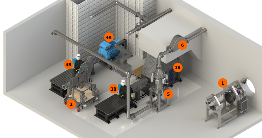
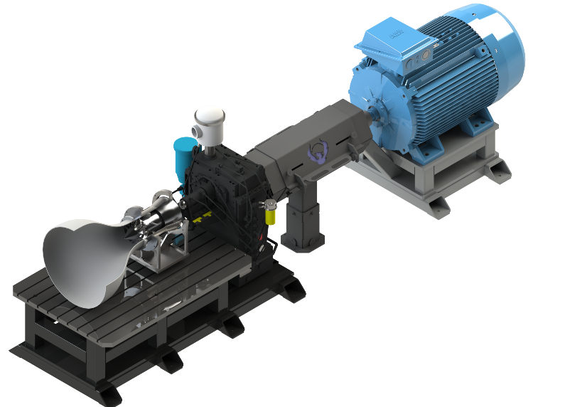
The layout of the facilities is depicted in the figure below and includes:
- Engines Thrust Stand
- Linear Cascade
- Rotational Turbine Facility
- Dynamometer
- Gearbox - 23 GR
- Fan/Compressor Facility
- ABB 315kW Electric Motor
- Gearbox - 15.5 GR
- TUTCO 0.5MW Electric Heater
- Coriolis Mass Flow Meter
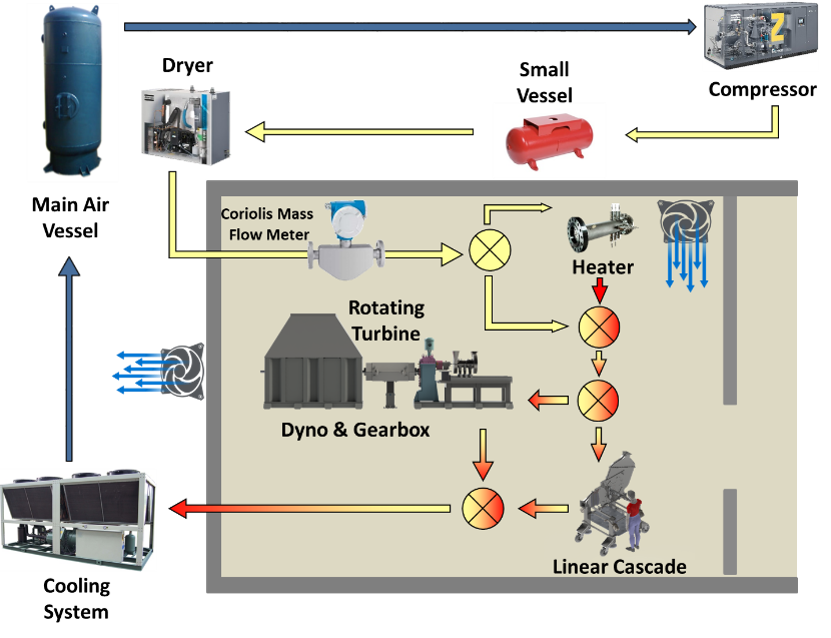
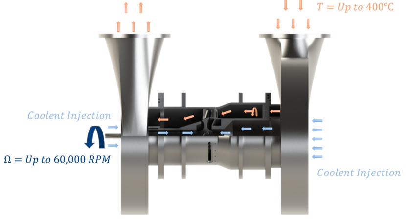
The turbine research facilities (linear cascade and rotational rig) are powered by an oil-free screw compressor with a variable speed drive that is capable of continuously providing mass flow rate of up to 1 kg/sec with a pressure ratio of up to 7:1 with a compressor inlet pressure in the range of 0.3-1 bar. The subatmospheric inlet pressure is achieved with closed loop operation. The air is then supplied into a 6 m3 pressure equalization tank, transferred through a drier, Coriolis mass flow meter and optional 510 kW electric heater that can raise the flow temperature to up to 700 K. After passing through the test section the air is cooled to a temperature of 300 K and collected in a large 24 m3 dump tank. The conceptual flow diagram and heater bypass can be seen in the images below.

- Continuous high-temperature operation at transonic conditions
- Max temperature: 350 ℃
- Flow periodicity on middle vane (no transverse spatial velocity and pressure gradients)
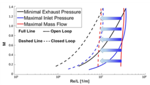
- Mach – Reynolds – Temperature Ratio independency
- 0 < M < 1.3
- 106 < Re/L < 3∙107
- Experimental robustness
- Variable incidence and stagger angles (±20° range for both)
- Accommodation of large flow turning angle range
- Simple vane replacement
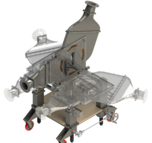
- Suitable for axial and radial turbine geometries
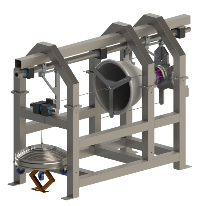
- Continuous high-temperature operation at transonic conditions
- Max speed: 90,000 RPM
- Max power: 280 kW
- Max torque: 60 Nm @ 45 kRPM; 30 Nm @ 90 kRPM
- Max temperature: 350℃
- Max turbine diameter: 300 mm
- Pressure ratio up to 7:1
- Maximum upstream pressure: 7 bara
- Minimum downstream pressure: 0.3 bara
- Turbine aerodynamic and heat transfer similarity
- Mach – Reynolds – Temperature Ratio independency
- Experiment Robustness
- 1 or 1.5 stage investigation
- Controllable swirl number adjustment
- Ease of assembly and test section replacement
- Suitable for axial and radial compressor geometries
- Technical specifications:
- Speed: 18,500 - 69,000 RPM
- Max power: 315 kW
- Max torque: 75 Nm @ 40 kRPM
- Max fan/compressor diameter: 300 mm
- Ease of assembly and test section replacement
- Versatile jet engine test stand
- Suitable for different engine types
- Can be operated with or without bellmouth inlet
- Supports up to 5kN of thrust
- Test stand features:
- Load cell
- Thrust transmitter
- Air bearings
- Modular engine support frame
- Removable load calibration system